Intro
Design
Airframe
Hardware
Software
Testing
Launch 5
Glossary
Links
Contact
Airframe
 The
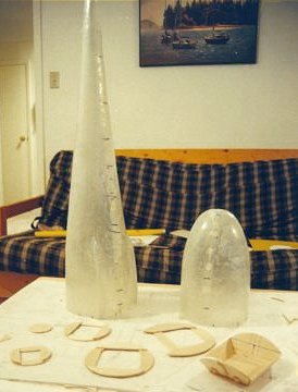
fuselage has a plywood and spruce internal structure, in a very thin fibreglass
shell. The
fuselage has a plywood and spruce internal structure, in a very thin fibreglass
shell.
It's also designed to seal water-tight with an O-ring where the nose cone mounts to the primary bulkhead, just ahead of the wing. This was tested and found (surprise) to actually work - it gained only a few tablespoons after 2 hours in the tub with a 2 kg load inside. The "guts rack", a frame on which all the electronics, servos, batteries, etc are mounted, is removable for testing and works as a single unit. (The guts-rack shown below was destroyed in the first kite-born test flight of the airframe.)
|
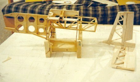 |
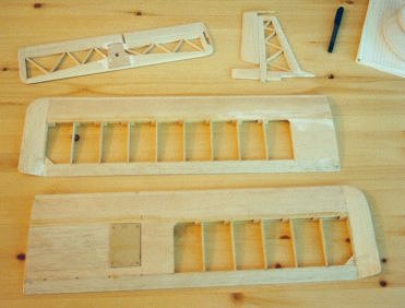 The tail is made of balsa, spruce and fabric covering construction, as was the first set of wings. The right wing has a plumbing hatch for the static/pitot tube. The second set of wings, not shown, were made foam-cored with vacuum-bagged fiberglass skins. |
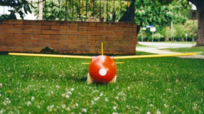 The finished airframe, with the first set of wings, which were designed for rudder-dihedral control. This was initially thought to be the most stable and conservative control method. [Yes, it's gaudy orange and yellow. I could tell stories about snazzy black, dark blue, white, or military camouflage small aircraft, but I won't, because they all involve losing sailplanes in the sky, mid air collisions, or very boring hunts in the woods that last for days.] |
|
|
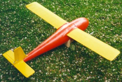 By the time the glider was ready for the first balloon launch, the simulator had shown it might experience control problems at the very high altitudes and speeds aimed for. But, by that point, it was almost ready to fly, so it seemed best to just go for it with a medium-altitude test. At the same time, plans were sketched up for a "Mark II" future airframe for the longer term, which would have the same basic design but different control methods and wing construction. [Deferring that redesign turned out to be a bad plan.]
|
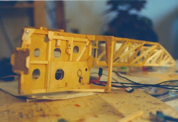
The GPS antenna goes at the end of the beam structure in its back, with the batteries mounted in the main part of the rear beam. Several instrument boards hide just behind the main cross frames, where the temperature is likely to be steadier, but most parts are bolted to the front beam, to help with overall balance issues. The fuselage's diameter was set by the need for 2-3cm of insulation. Assembling all the oddly shaped boards and parts into the small space left was a bit like doing one of those wooden block puzzles (Check out the bottom of the hardware page). |