Intro
Design
Airframe
Hardware
Software
Testing
Launch 5
Glossary
Links
Contact
Hardware
|
This board also provides a controllable 5v bus for the cameras, and a tap for monitoring the input battery voltage. All non-essentials are provided with fuses. There is a sleep trigger and wake timer on one battery plug, that lets the glider save some battery capacity for transmitting its position several times a day if it crashes or lands out.
|
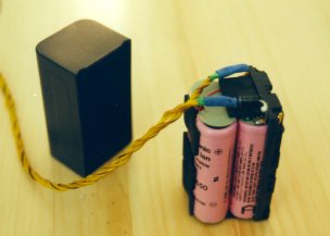 The
battery packs are Lithium rechargeable camcorder packs, with 3-amp diodes on
their positive terminals. The resulting voltage drop caused by the diodes doesn't waste much power,
as most of it would be dissipated on the power board anyways. But it does isolate the batteries from each
other, and
provide some extra warmth in the battery compartment and instrument bay. The
battery packs are Lithium rechargeable camcorder packs, with 3-amp diodes on
their positive terminals. The resulting voltage drop caused by the diodes doesn't waste much power,
as most of it would be dissipated on the power board anyways. But it does isolate the batteries from each
other, and
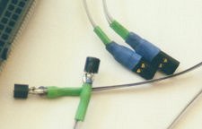
provide some extra warmth in the battery compartment and instrument bay. The batteries were a bit expensive,
but have been very impressive. The power density is just awesome, as is their
tolerance to cold. Note the dual power-wires from each battery terminal.
The
sockets at the plug end have twinned contacts as well. |
|
Because the PC-104 has an allowed temperate range of only 0c to 70c, the
computer and bus board are enclosed in a box made of stiff metalized mylar.
Along with about a dozen small chokes, this also helps protect against RFI. |
|
A step-up DC-DC converter circuit is used on the power supply board to provide radio power, and the large power diodes on the battery packs also stop them from providing too much voltage to the DC-DC converter when at peak charge. The ground station also uses the same model of radio and modem, but with the radio supplied with 9.6v, which allows it to give its maximum output (but with a higher current draw).
|
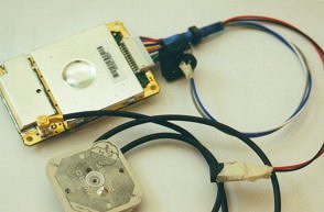 The
GPS is an OEM 12-channel receiver from Garmin, the GPS-25. It has an internal
temperature sensor, and is used with the passive antenna shown. There has never been a
problem with this gadget, despite the antenna being mounted very close to the
UHF telemetry antenna in the horizontal stab. The
GPS is an OEM 12-channel receiver from Garmin, the GPS-25. It has an internal
temperature sensor, and is used with the passive antenna shown. There has never been a
problem with this gadget, despite the antenna being mounted very close to the
UHF telemetry antenna in the horizontal stab. |
|
|
|
|
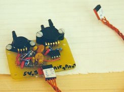
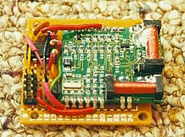
The twin cut-down driver boards are on top left, and one of the
cut-devices on top right. Each driver board takes 3
digital input lines, and is fired by the right combination of arm (low)
and trip (high), causing it to short the separate 50mah nicads through the
cut device via a relay. There are pull-up and pull-down resistors to prevent a false
trigger if the command lines come loose, and opposite logic levels
for the arm and trip lines help avoid accidental release due to RFI. The cut-devices for the tail release and chute release are twin small stretches of nicrome wire strung between metal posts, which melt through nylon chord in about 1/2 second. Each driver board is connected to one tail release and one chute release, so overall this system is dual-redundant and fail-safe. As long as the nicads are above -15c, this setup has been perfectly reliable in dozens of uses.
|
|
|
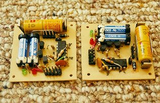
The left photo is the Pitot / Static pressure sensor board. Note that it's a bit
of a mess - the circuit design was changed a somewhat after the PCB board had already
been made. It has proven to give repeatable and reliable readings, with very
little RFI sensitivity.
The right photo is of the internal and external temperature sensors, based on the LM134 by National semiconductor. These have generally worked great, and are easy to calibrate, but turned out to be the most sensitive instrument to RFI. It's a puzzle as to why this is true, because they work with a 2-wire current-based analog lead, which should be much less sensitive than a voltage-based lead. The problem was reduced by means of a great deal of attention to shielding.
|
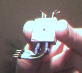
 The
compass is a Vector 2x Compass Module,
which is easy to interface, but required a few more IO pins than were available to it.
So, 2 pins were saved by having a 555 timer trip the reset sequence if it
isn't used for more than a couple of seconds. The
compass is a Vector 2x Compass Module,
which is easy to interface, but required a few more IO pins than were available to it.
So, 2 pins were saved by having a 555 timer trip the reset sequence if it
isn't used for more than a couple of seconds.It also has an issue in that it is fixed to the aircraft's orientation, not the ground's. Because the earth's magnetic field is inclined steeply in the northern hemisphere, that means when the aircraft pitches up or down, or turns steeply, the compass output is hopelessly off. |
|
|
|
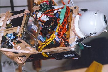
Typical systems-assembly and testing scene.
|
|
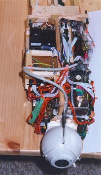
How the whole guts-rack goes together. You can also see |
|
|
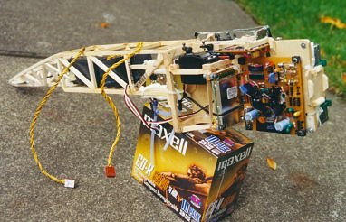
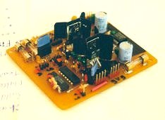 The
power board provides 8.15v at 1 amp (peak) for the radio, and up to 3 amps at 5v
for the remainder of the systems. The 8.15v source is a DC-DC converter, but
simple low-drop out voltage regulators turned out to be best for the
5v source. There are no critical paths here; the dual 5v regulators are arranged
(and tested) so no one broken connection or failed part, and few shorts, can result in losing 5v bus power.
The
power board provides 8.15v at 1 amp (peak) for the radio, and up to 3 amps at 5v
for the remainder of the systems. The 8.15v source is a DC-DC converter, but
simple low-drop out voltage regulators turned out to be best for the
5v source. There are no critical paths here; the dual 5v regulators are arranged
(and tested) so no one broken connection or failed part, and few shorts, can result in losing 5v bus power. 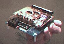
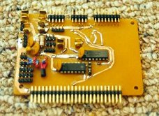 It's
shown above with the bus-board, also shown on the right. This board distributes
the various I/O resources to the instruments and controls. It also provides
current limiting or fuse protection for low-power sub-systems for which draw
their power from
the bus-board.
It's
shown above with the bus-board, also shown on the right. This board distributes
the various I/O resources to the instruments and controls. It also provides
current limiting or fuse protection for low-power sub-systems for which draw
their power from
the bus-board.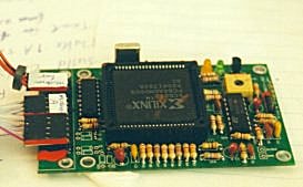 The YAM packet radio modem works at both 2400 and 9600 baud. With
packet overhead, and duty-cycle restrictions on the TEKK radio, the actual
maximum baud rate is more like 3600. It relies on some little-used PC serial port pins which
the PC-104 computer doesn't have, so it was a bit of a pain to write the
driver code. The main issue was that an interrupt based driver couldn't
be made to work with it, so instead a polling-based one had to be used, which caused side
effects with other peripheral drivers.
The YAM packet radio modem works at both 2400 and 9600 baud. With
packet overhead, and duty-cycle restrictions on the TEKK radio, the actual
maximum baud rate is more like 3600. It relies on some little-used PC serial port pins which
the PC-104 computer doesn't have, so it was a bit of a pain to write the
driver code. The main issue was that an interrupt based driver couldn't
be made to work with it, so instead a polling-based one had to be used, which caused side
effects with other peripheral drivers.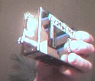 The TEKK data radio has a fixed, crystal controlled frequency in the amateur
(ham radio) UHF
(70cm) band. It has a maximum output of 2 watts, at which it consumes about 10w.
The onboard radio gives it 8.15v to put out about 1w, which is a bit of an
awkward voltage requirement, being a bit below the peak voltage of the lithium
battery packs raw output, yet well above their voltage when near dead.
The TEKK data radio has a fixed, crystal controlled frequency in the amateur
(ham radio) UHF
(70cm) band. It has a maximum output of 2 watts, at which it consumes about 10w.
The onboard radio gives it 8.15v to put out about 1w, which is a bit of an
awkward voltage requirement, being a bit below the peak voltage of the lithium
battery packs raw output, yet well above their voltage when near dead.